Literal Interpretation of Scope of Right
I. Trial for Invalidation of Patent Registration No. 420834
Patent Court's Decision No. 2005HE03277 published on Mar. 24, 2006
Supreme Court's Decision No. 2006HU848 published on Oct. 12, 2007
- returned for retrial
1. Gist of the present patented invention (claim 1)
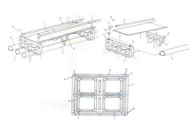
A wave resistant cage apparatus in an assembly type in which a buoy pipe (3) is bent to be operatively installed by a buoy connection elbow (4) interposed at a corner (R) of the buoy pipe (3), the buoy pipe (3) is inserted to be operated by a through hole (2) formed in a buoy bracket (1) and a work footboard (7) is connected to be fixed onto the buoy bracket (1),
the apparatus characterized in that,
a foot support (6) with arc connection parts (5) formed at the middle and both sides of the foot support (6) is positioned between the buoy brackets (1) at a predetermined distance,
one side of each of the buoy pipes (3), which are inserted into the through holes (2) of the buoy brackets (1) and horizontally installed, is connected to the arch connection parts (5) formed at the middle and both sides of the foot support (6) and horizontally installed,
the work footboard (7) is positioned on the foot support (6), and
an end of each of handrail supports (10) is inserted into each of support connection openings (9) formed at both sides of the buoy bracket (1), so that a handrail (12) is horizontally installed.

2. Supreme Court's decision (2006HU848)
The claim(s) shall describe the matter(s) to be protected as a patent. The scope of protection of the patented invention is decided by the matter(s) described in the claim(s). Thus, the technical constitution of an invention to determine the requirements for patentability is finally decided based on the description of the claim(s). Unless there are any special reasons, it is not allowable to finally decide the technical constitution of the invention by limiting it to a specific embodiment(s) disclosed in the detailed explanation of the invention or drawing(s).
In the present patented invention, the foot support includes the arc connection parts formed at the middle and both sides of the foot support. The foot support is installed between the buoy brackets at a predetermined distance. One side of each of the buoy pipes is inserted into and horizontally installed in each of the through holes of the buoy brackets. The buoy pipes are connected to the middle and both sides of the arc connection parts, thereby controlling the side directional floating and rotation directional floating of the buoy pipes. However, the claims do not make any indication as to whether the foot support is made in a single body with the arc connection parts or it is
separable/connectable. Therefore, the technical constitution of the foot support in the present patented invention can be finally decided as including both the form that the foot support is made in a single body with the arc connection parts and the form that the foot support is separable from and connectable to the are connection parts. That is, the technical constitution of the foot support cannot be interpreted narrowly/restrictively as the foot support (6) formed in a single body with the arc connection parts as merely shown in the embodiment described in the drawing(s) attached to the application of the invention.
II. Trial for Confirmation of Scope of Right of Patent Registration
No. 485763
Patent Court's Decision No. 2006HE07986 published on Jul. 5, 2007
- finally decided
1. Gist of the present patented invention and the cited invention
(1) Present patented invention (claim 1)
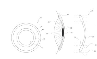
A rigid gas permeable (RGP) lens having high oxygen permeability comprising:
- an optical unit including an inner side corresponding to a cornea of an eye (hereinafter, referred to as `constituent 1');
- a tear drop storage formed to be close to a circumferential surface of the optical unit (hereinafter, referred to as `constituent 2');
- a peripheral part formed to be close to the tear drop storage (hereinafter, referred to as `constituent 3'), and
- an edge part formed nearly to an outer circumference of the peripheral part. (hereinafter, referred to as `constituent 4'),

(2) Cited invention
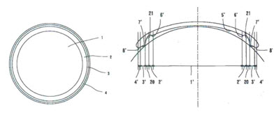
In the cited invention, there is disclosed the constitution of: lens middle zone (1) having a base curve (5') in a concave shape, second and third middle zones (2', 20) each formed at an outer side of the lens middle zone (1) and storing tears in a plurality of middle curves, first middle zones (3, 3') formed in connection to the second and third middle zones (2', 20), and peripheral zones (4, 4') formed in connection to the first middle zones (3, 3'). Specially, there is the constitution of additionally storing tears in the second and third middle zones (2', 20) formed by the plurality of the middle curves (6', 7' 21) formed between the base curve (5') and the peripheral curve (8').

2. Patent Court's decision (2006HE07986)
(1) Method of finally confirming the scope of right
The scope of a patent right is defined based on what is described in the claim(s). Thus, in determining the question as to whether there is a reason why an invention cannot be patented, if the scope of the right is clear based on the description of the claim(s) only, the question shall be determined based on the description of the claim(s). The question shall not be determined by narrowly/restrictively interpreting the claim(s) based on the description of the detailed explanation of the invention or drawing(s).
(2) Only based on the description of the claim(s), constituent 2 can be clearly understood as meaning ‘the constitution of forming the tear drop storage to close to a circumferential surface of constituent 1’. Thus, constituent 2 shall not be narrowly/restrictively interpreted as meaning ‘the constitution which is formed without changing the base curve and in which the width of the storage is narrow’, based on the other description of the detailed explanation of the invention or drawing(s).
Constituent 2 of the present invention is formed to be adjacent to the circumferential surface of constituent 2, and the second and third middle zones of the cited invention are formed to be adjacent to the circumferential surface of the middle zone of the lens corresponding to the same constitution of constituent 2. Thus, these constitutions are identical with each other with respect to the location and shape. Further, constituent 2 has the action of collecting tears and storing the tears between the cornea and the lens, and the second and third middle zones of the cited invention has the action of additionally storing lots of tear liquid between the plurality of middle curves (6', 7' and 21) and the cornea surface (10). Thus, these constitutions are also identical with each other with respect to the actions. Accordingly, constituent 2 of the present invention is considered as being identical with the second and third middle zones of the cited invention, with respect to the technical constitution.
III. Appeal against Decision to Reject Patent Application
No. 2002-57952
Patent Court's Decision No. 2006HE08798 published on Jun. 22, 2007
- finally decided.
1. Gist of the present patent invention (claim 1)
A multi-direction wind power generator which is generated by predetermined wind power, comprising:
- a base frame including a central shaft in the middle part and supported to the ground, wherein a space of a predetermined radius is formed around the central shaft (hereinafter, referred to as ‘constituent ①’);
- rotation shaft fitted into the central shaft of the base frame to rotate (hereinafter, referred to as ‘constituent ②’);
- a number of upper/lower support frames positioned, at a pr
|